 |
 |
 |
|
< < Back to Outfitting
Photo Essay of C-1 Outfitting
Table of Contents:
Looking Forward Contact Author
Introduction: Return to Table of Contents This is a fairly complicated installation. I feel that the time spent on the installation was worth it to me, largely because the rig can be quickly removed and reinstalled in a different boat. All the components of the rig are attached to the boat without the use of glue. In this boat, all fasteners go through factory holes in the boat from the kayak outfitting. Also, all facets of the outfitting are fully adjustable. The basic idea shown here is to take a piece of hollow, square, PVC tubing, and run it down the middle of the cockpit of the boat. The tube, or rail, is attached to the boat using two straps that run across the inside of the hull of the boat. One strap is located forward of the cockpit, the other is located under the saddle near the back of the cockpit. The rail is used as a base for the saddle, for storage, and as a structural component of the thigh strap system. It could also be the base for foot braces. I attached my foot braces to the aft cross-strap, since my feet wanted to be more outboard in this boat.
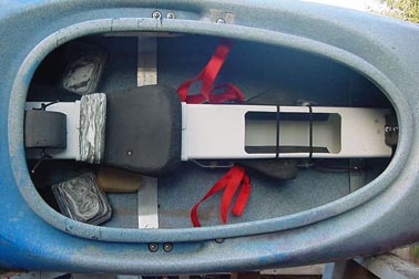
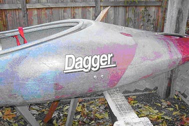
Overview of the rig installed in the boat. The large size of the fence post seemed like a drawback at first, but I now believe it to be a bonus. There is room inside the resulting fence rail in the boat to store a first aid kit, a lunch bag, a water bottle, and some extra clothing it all fits inside the rail. The inside of the rail is wide open along its entire length. However, I have slim legs and a thirty inch seam. The Redline that I converted has a large cockpit. Paddlers with larger legs and/or a boat with a small cockpit should mock up the outfit before committing to the 5 fence post. Smaller fencing components are available, and could work with some modification of the design.
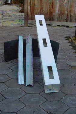
The basic stock for the rig:
5 vinyl fence post used as a rail up the middle of the boat The fence post shown is an end post this has the fewest slots cut into it at the factory. I used the end not in this photo, it is in the boat, because it had no factory slots in it. Shown here is the left over end. The vinyl fence post is actually made from PVC (polyvinylchloride,) just for the record. Tools used:
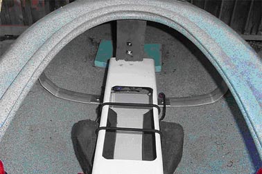
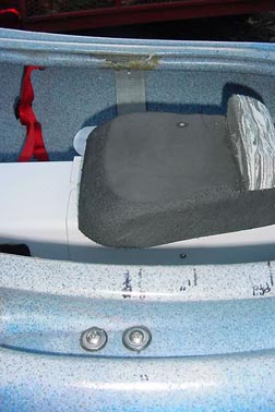
Circular saw with carbide blade - to cut both aluminum and plastic stock I also used a small drill press and a belt sander along the way, these speed up the process if you have them available. View from behind cockpit looking forward.
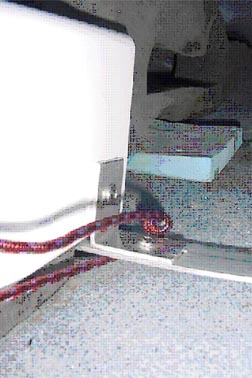
The knee pads are not installed, for clarity in the photos. I am just using a flat sheet of 1 minicell for knee pads. It is 10 x 24, and slips under the rail to offer padding for both knees. Close-up of the forward fence rail mounting assembly.
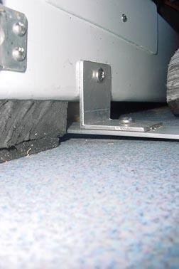
The rope showing in the photo is just a scrap tied in to allow dry bag attachment, etc. By looking at this photo, and the previous one, the location of this photo can be deciphered. Note the gap between the boat and the fence rail. Most, if not all, boats will have some rocker in the length of their cockpit. The fence rail should not create any hard spots inside the hull. Short pieces of aluminum angle stock were cut and used as brackets. The fence rail is held up in the boat, so that at its fore and aft ends do not touch the hull. After all installations were complete, minicell scraps were slipped under the rail to give support to the hull. This could be skipped in a newer boat but the Redline that I converted is a beater-boat, and benefited from some padding installed to reshape the curve of the hull. Close-up of forward cross-strap fastening to boat.
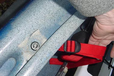
Wing nut and bracket under the cross-strap are parts from the factory kayak foot brace fastening system. Exterior view locating factory fasteners for the original kayak foot braces on the converted Redline.
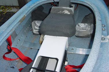
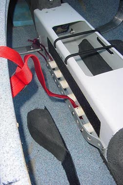
Looking down into boat from forward of cockpit, looking aft.
Looking across boat, port to starboard (left to right).
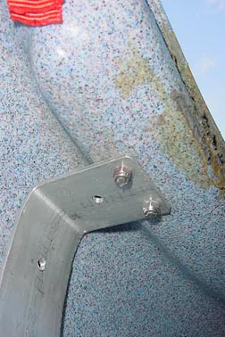
The screws in the foreground of this photo are used to attach the aluminum cross-strap that hugs the interior of the boat, under the saddle. The aluminum strap inside the boat on The left side of this photo curves up under the deck and is attached with two similar screws on that side of the cockpit. These are the factory screws from the kayak seat assembly. View up from the inside the cockpit, showing the boat attachment of the aft cross-strap.
Close-up of the aft fence rail attachment, to the cross-strap running along the inside of the boat under the saddle.
Notice that the cross-straps don't have to fit the hull perfectly. Also showing in this photo are the small screws used to locate the saddle brackets on the fence rail. Close-up on adjustable saddle components.
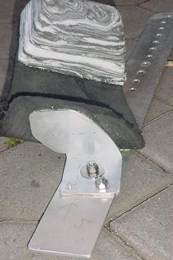
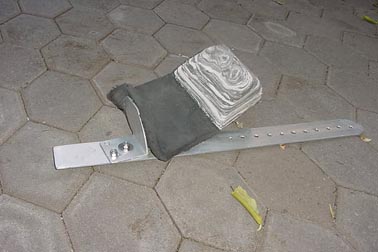
A ten inch long section of the fence post material was cut to create two large L-shaped sections. The two L's are connected by a pad of minicell, using high-quality contact cement. One screw on each side of the rail, going through the L-shaped brackets, connect the saddle assembly to the rail. Multiple holes in the rail, under the bracket, allow saddle adjustment on the river. Close-up on upper attachment for thigh strap.
The screw runs through the deck, then through a large washer, then through the strapping, another large washer, and into a nylock nut. The holes in the strap are melted with a piece of wire that is red hot. One piece of strapping is doubled through the non-running part of the ladderlock and fastened to the boat with the screw. Another piece of strapping runs from the ladderlock, under the rail, and up to another ladderlock attached on the other side of the cockpit. The screws are in factory holes that were used to install the kayak's thigh brace components. Wimpy 1 strapping to be replaced with 2 as soon as I get my hands on some larger ladderlocks! Close-up of adjustment stations for lower end of thigh straps.
OK, I lost it here! The aluminum strap running along the fence rail is an old piece of predrilled foot brace from the original kayak rig. It is installed on the fence rail with bolts that go though CPVC tubes. The CPVC tubes are sold as adapter bushings in the plumbing section of the hardware store. Anyway, this installation allows one to move the strap forward or back, simply by pulling it out of one ladderlocks, and reaving it through a different slot along the sides of the fence rail. Also showing in this photo are the adjustable knee-spreading-pads. A long piece of Velcro is used to attach the wedge-shaped minicell pads to the sides of the fence rail. By moving the location of the pads fore or aft, one can adjust the fit of the boat to the legs. Close-up of foot brace installation in boat.
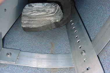
A piece of 2 aluminum strap is drilled for adjustment holes. This is attached to the aft cross-strap with a Ό screw running into a threaded hole in the boat strap. The screw is just the right length to do the job, and not long enough to mar the inside of the hull. Foot brace assembly pulled out of boat. View from aft looking forward.
Components include 2 strap with adjustment holes, 2 angle stock fashioned into base for foot padding, and minicell padding. I like a large ankle pad, so I leave my foot padding long forward and glue the ankle pad to that. I paddled the boat and changed the angle of the foot bracket on the adjustment strap a bit before finding the best angle for me. The second bolt keeps it where I like it. More views of the foot brace assembly follow:
Closing Comments: I have only been on the river in this converted boat for a few hours, on a class II training stretch with one play wave. This is the third boat that I have outfitted, and I still find myself tweaking the location of all the components after an hour on the river no matter how good the rig feels in the workshop. I really enjoyed being able to move my thigh straps and leg pads in less than a minute while sitting in an eddy. Moving the foot braces forward took two minutes, on the beach. The boat already fits me better than my year-old Cascade rig. The rig looks to be plenty strong overall! However, the pressure on the foot braces has torqued everything back a quarter inch or so, and the angle brackets attached to the fence post rail have rotated slightly as a result. The cross straps look slightly crooked along the hull. It may be nothing, but I may have to put a diagonal in between the two cross straps in the long run. Time will tell. I floated the boat in flat water to locate my saddle position. Instead of positioning the saddle to give a common distance from the bow to the water and the stern to the water while sitting upright, I tried this: I positioned the saddle to give a common distance from the bow and stern to the water when I was leaning well forward and backward. In other words, I have an equal ability to bury the bow and the stern. This method gave a saddle position that was quite a bit different from the position selected by sitting upright in the boat. I think it is a superior position. If anyone actually made it this far in reviewing this material enjoy and good luck. I would enjoy hearing from anyone that has used ideas from this posting to outfit a C-1 or OC-1. Email me with any feedback! I can improve this posting and my next conversion with any ideas. Of course, I will include your name and contact info on any ideas posted, if you wish.
Randy Foster Subsequent updates: After several trips in the new conversion, I have found that the diagonal members mentioned above are indeed necessary. The pressure on the foot braces while paddling has moved the entire assembly aft at the bottom a little bit, twisting all the attachment points slightly. To remedy this, I have tied a piece of webbing on each side. The webbing loops around the forward boat-to-cross-strap attachment point, and runs down to loop around the rear cross strap at the attachment point for the foot braces. These straps are tied very tightly, and are successfully keeping everything in position. The next time I have the rig out of the boat for some reason, I will replace the webbing with something more permanent.
|
|
|
CBoats.net is managed by Adam Pearsall and Kenneth Sarzynski
with graphic artwork by Sara Pearsall
© 2025 by CBoats.net - all rights reserved. Materials found on this website can only be used for personal use. |

